
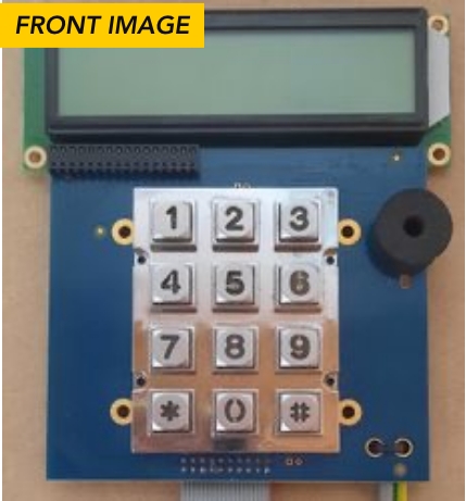
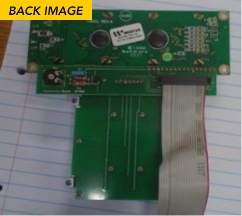
Comb Keypad and Display assemblies.
This page describes all variants of the Comb Keypad and Display assemblies. The document lists the changes between the versions and the applicable Engineering Change Notices (ECN).
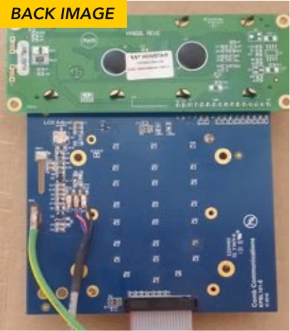
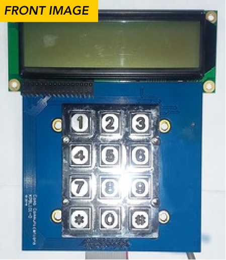
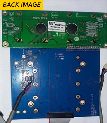
PCB VERSION: KPBL101-F

Features
-
Keypad directly mounted onto Keypad/LCD PCB.
-
Fixed missing track between amplifier and output capacitor on KP101-E PCB.
-
Backlight keypad.
-
Added ESD diodes to protect Intercom from static discharge.
-
Onboard microphone.
-
Pluggable LCD module.
Compatibility
-
MK II NS
-
MK II Lite
-
MK II BBH
- MK II BB
APPLICABLE ECN’S
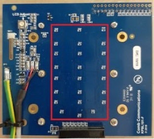
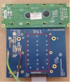
Remove the following diodes from the PCB: D17, D20, D21, D24, D25, D28, D29, D32, D33, D36, D37, D40, D41, D44, D45, D48, D49, D52, D53, D56, D57, D60, D61, D64
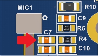
Check R10 for placement. If not fitted, fit a 10ohm 1206 SMD resistor.
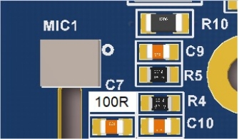
Remove the capacitor C7.
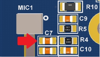
Place the 0805 100ohm resistor.

PCB VERSION: KPBL101-E

Features
-
Increased the size of the contrast variable resistor.
-
Keypad directly mounted onto Keypad/LCD PCB.
-
Backlight keypad.
-
Added ESD diodes to protect Intercom from static discharge.
-
Onboard microphone.
-
Pluggable LCD module.
Compatibility
-
MK II NS
-
MK II Lite
-
MK II BBH
- MK II BB
APPLICABLE ECN’S
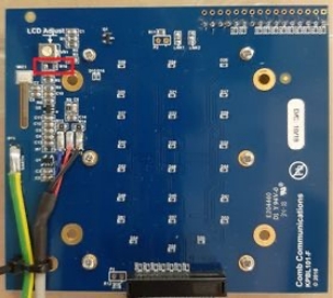
Add a wire bridge between Pin 1 of U2 and R9

Remove the following diodes from the PCB:
D17, D20, D21, D24, D25, D28, D29, D32, D33, D36, D37, D40, D41, D44, D45, D48, D49, D52, D53, D56, D57, D60, D61, D64
Check R10 for placement. If not fitted, fit a 10ohm 1206 SMD resistor.

Remove the capacitor C7.
Place the 100ohm 0805 resistor.
PCB Version: KPBL101-D
Features
-
SMD contrast control.
-
Keypad directly mounted onto Keypad/LCD PCB.
-
Backlight keypad.
-
Onboard microphone.
-
Pluggable LCD module.
Compatibility
-
MK II Lite
-
MK II BBH
-
MK II BB
PCB Version: KPBL101-C
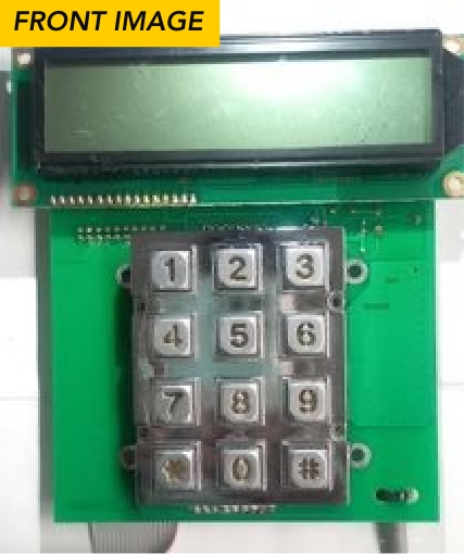
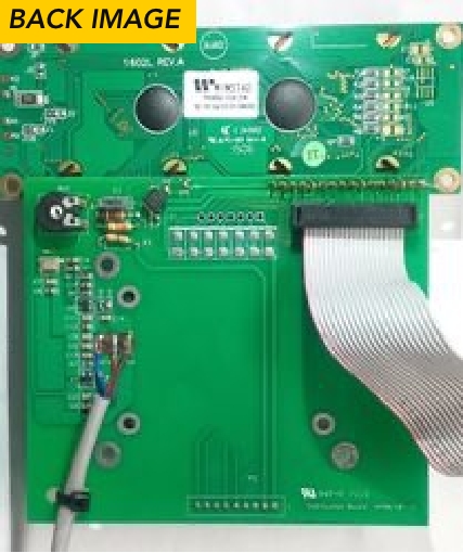
Features
-
Standard contrast control.
-
Keypad PCB is separate from Keypad/LCD PCB.
-
Backlight keypad.
-
First iteration of the onboard microphone.
Compatibility
-
MK II Lite
-
MK II BBH
-
MK II BB
PCB VERSION: KP202

Features
-
Simple PCB to interface ribbon connector to the keypad and LCD.
-
Standard contrast control.
-
No backlight keypad.
-
No onboard microphone.
Compatibility
-
MK II BBH
- MK II BB

Find an Installer
Our approved installers are trained and accredited to ensure success with every installation.

Find a Distributor
Our approved installers are trained and accredited to ensure success with every installation.

Need Advice
If you can’t find a solution online, reach out to one of our consultants for professional advice.


